The SSE (Super Sport Estate) Project
Posted: 24 Jan 2008 12:52
I thought I would start a project thread on my wagon , after mentioning it on the Miata rear end thread. I always wanted to do this to a wagon- A wagon that would handle like a sedan, that I could do track days if I wanted to. I am starting with a 1969 Nevada car- no rust. My plan is a fully independent,R-180LSD, VQ-35DE, 6-speed, 300zx brakes. I also want to keep the weight down as much as possible. Here is the car, it is totally stock. In this picture I was seeing if the Rays wheel might fit.

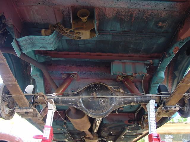
This is a picture of the stock rear end, I plan having a "H" sub frame that goes between the two frame members where the bump stops hit on the stock frame member. The entire frame hoops will be reinforced to support the weight of the car.
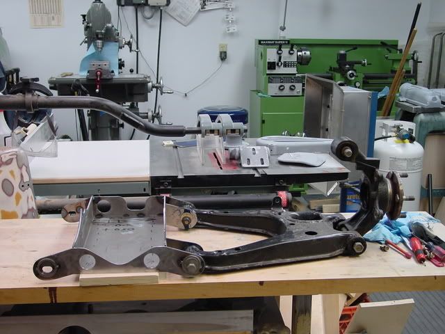
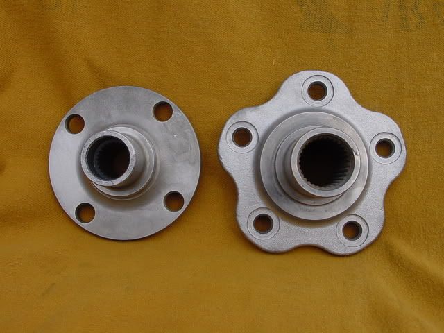
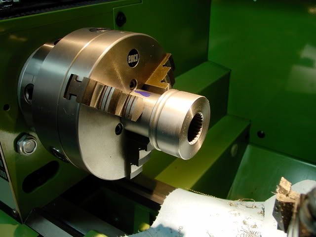
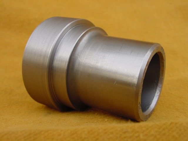
After brain storming on what do do about fabbing a IRS from scratch, i wanted a A arm type setup with coil-overs i.e. open wheel race car. The most work I thought would be fabbing the uprights with line boring for the bearings and all. One day I was at a friends shop where he had a Miata up on the lift. I thought that this might be a start towards the IRS, A- Arm setup,a small car, light, and people race them, so the basics of the rear end must be good. I then located a fire damaged Miata at a yard and purchased the rear assy. After a clean up, the work started. The first problem is that Miata, even though it is a pretty small , the rear end is 5" wider than the stock wagon rear end. So instead of modifying the Miata A-arms, I decided to start from the center and work out towards the wheels. This is a pic of the start, notice the rear end is R-160, I will be using R-180 from a STI to handle the power from the VQ.

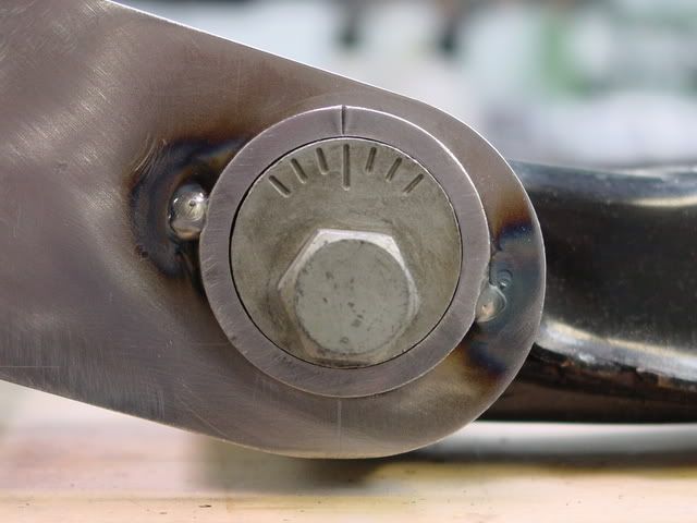
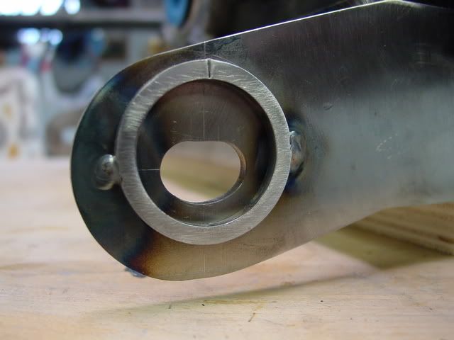
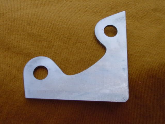
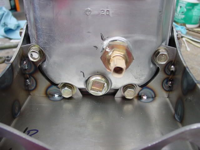
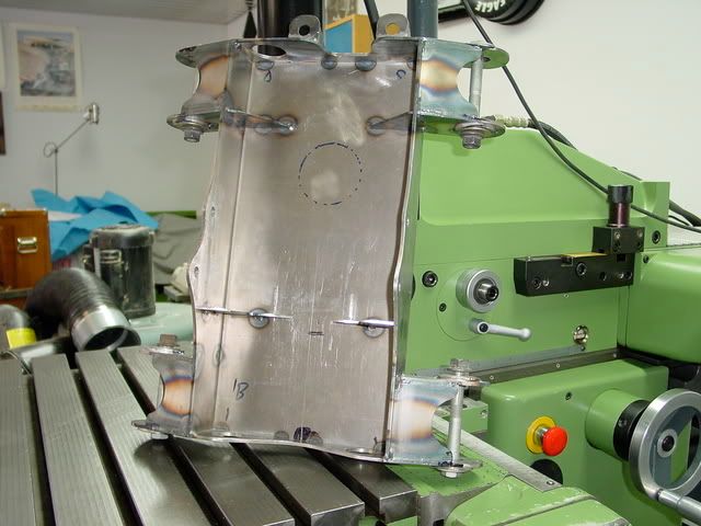
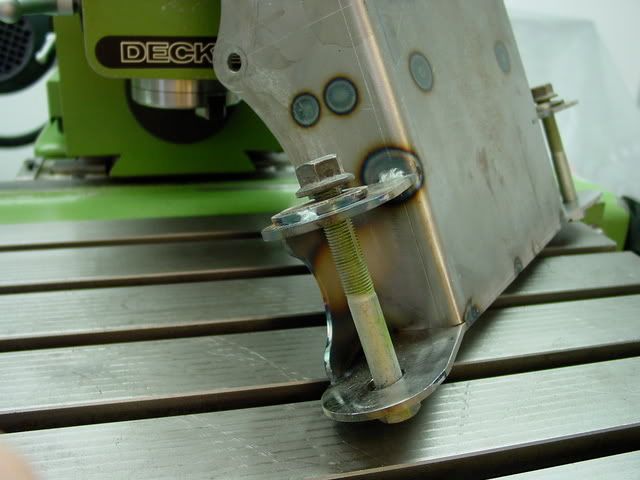
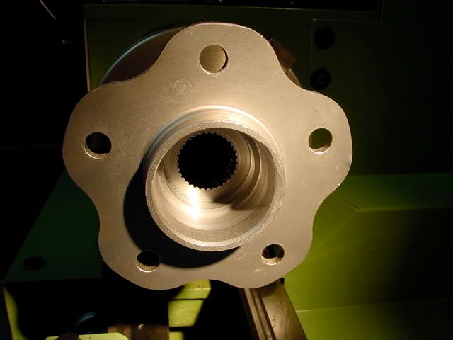
This is the start of the lower sub frame thats bolts to the R-180, front , side cover, end rear cover. It was real pain to get the "u" bent so it fits correctly to the side of the diff. with no spacer. You can see by the marking we are in the 0.00 to +0.030" spec.

More pictures to follow in the near future.
Monte
This is a picture of the stock rear end, I plan having a "H" sub frame that goes between the two frame members where the bump stops hit on the stock frame member. The entire frame hoops will be reinforced to support the weight of the car.
After brain storming on what do do about fabbing a IRS from scratch, i wanted a A arm type setup with coil-overs i.e. open wheel race car. The most work I thought would be fabbing the uprights with line boring for the bearings and all. One day I was at a friends shop where he had a Miata up on the lift. I thought that this might be a start towards the IRS, A- Arm setup,a small car, light, and people race them, so the basics of the rear end must be good. I then located a fire damaged Miata at a yard and purchased the rear assy. After a clean up, the work started. The first problem is that Miata, even though it is a pretty small , the rear end is 5" wider than the stock wagon rear end. So instead of modifying the Miata A-arms, I decided to start from the center and work out towards the wheels. This is a pic of the start, notice the rear end is R-160, I will be using R-180 from a STI to handle the power from the VQ.
This is the start of the lower sub frame thats bolts to the R-180, front , side cover, end rear cover. It was real pain to get the "u" bent so it fits correctly to the side of the diff. with no spacer. You can see by the marking we are in the 0.00 to +0.030" spec.
More pictures to follow in the near future.
Monte