Chasing J's
-
tr6racer21
- Supporter
- Posts: 307
- Joined: 07 Mar 2008 10:18
- Location: Richmond, VA
Chasing J's
Anyone using Chasing J's Product line either on the street or the track. Looks like top shelf fabrication. Looking for honest comparison type feedback if available. Most notably the front strut redesign is interesting, but not sure that bump steer claims are substantial as no concrete data or specs are provided. Limited or one-off designs can be problematic especially for the race crowd as parts wear more quickly and common replacement parts/pieces are essential. It looks as though the T/C rod they offer is very substantial and easily adjusted, but not sure if the seemingly shorter than stock travel arc is beneficial. Then how do all the redesigns work with a lowered car which still has the original pick-up points and thus positive camber gain issues. What kind of clearances have been created by moving the spindle up on the strut. Wouldn't the steering knuckle clearance with smaller wheels still be a problem? Just looking for some specs, data, opinions, etc.....thanks
Re: Chasing J's
I had to search quite a bit to even find Chasing J's…
http://www.pikore.com/chasingjs
Is there another site to look at? This is all I found in my search.
I concur that the strut rod design on their Pikore page look much better than a couple of the alternatives out there, but until you hold something in your hands... At least the design does not include a rod end on the LCA connection side, which has been an engineering fail design from the start. I see that even Chasing J's takes a shot at the previously mentioned design.
The new strut design looks interesting, but there is nothing more than a single shot. Agreed that from a machinist and production point of view, a new hub and spindle assembly could be mass produced with very little effort these days and maybe long overdue. It appears the new spindle/hub design use a more modern bearing cartridge arrangement - certainly easy from a design and manufacturing point of view, and if one utilized a newer FWD type bearing cartridge, most are pretty beefy compared to the 510 or ZX designs. Not that I have ever experienced a failure on a ZX spindle mind you, but from a production stand point, it makes sense. I look forward to hearing/seeing more.
So - who are Chasing J's anyways? Usually a company doesn't just appear, there much be someone behind this that we all know. Anyone have some information or a link to a better site?
Byron
Love people and use things,
because the opposite never works.
because the opposite never works.
-
tr6racer21
- Supporter
- Posts: 307
- Joined: 07 Mar 2008 10:18
- Location: Richmond, VA
-
tr6racer21
- Supporter
- Posts: 307
- Joined: 07 Mar 2008 10:18
- Location: Richmond, VA
Re: Chasing J's
My thing is there are claims made which are not substantiated nor are any specs provided. If your going to make claims then provide comparisons, data, and specs for us to look at before clicking the buy button.
Re: Chasing J's
Thanks for the link. (duuhhh chasingjs.com...sorry, but I obviously had a dull moment for not attempting that this morning).
I did however put some thought into a response this morning - grab a coffee....
Agreed that there are claims on the strut design that are unfounded. I find it interesting that they claim that bump steer spacers don't work, yet in practice their dropped spindle design is geometrically achieving the same thing..... Am I missing something here?
It's a fabricated part from scratch, and there are a few design parameters that are interesting. First off let’s look at the original part, being 280ZX, 510, M30 or whichever OEM base strut you might start from- these are forgings. Forging is a hot forming process that forms metal into a shape while keeping its grain structure more less intact while getting the shape of the part your require. The rough shape of an OEM spindle is forged out of an ingot, and then finish machined to the final product which includes the spindle, brake caliper mount, the strut tub base (in which the strut tube itself is then later welded) and the steering are mount at the bottom. This is all one part, originally forged as a unit.
This spindle is a fabrication, in other words it’s a number of parts that are assembled together by weldments. I see 4 individual weldments on this part, a strut tube base, a strut tube, a spindle, a brake caliper mount and a steering are flange – all individual pieces then welded together to make a part.
My first question – as in specification you’re mentioned by the original post – what materials are utilized in all these individual parts?
The spindle itself would be my first concern. The original material is a strong metal alloy specifically made to not only hold shape under heat utilized in the forging process, but is also alloyed to allow the molding of the material somewhere close to its austenitic temperature range, a temperature that depending on the carbon content is where the material loses it’s magnetic properties, but mostly allows the material to be elastic enough to flow in the forging process while maintaining a grain structure that is uniform. Because the forging process is completed at such a high heat range, a cooling process that creates a heat treatment in the part is then possible on the cool down cycle of the whole process. In the end you have a uniform part with an integral grain structure.
On this new component, what material is the spindle made out of? If it’s a HTSR material of a specific allow (Heat Treated and Stress Relieved), it would share similar properties to the OEM spindle. So this is a question to ask. If the material is a higher carbon alloy, then what is the welding process utilized, and is there any after treatment? This would quickly back up the first question.
This strut itself a weldment, and I’m certainly not saying a weldment is poor engineering in any way. There are a number of guys out there in our community running spindles where the brake mounting ears were cut off and new ones welded on. But it does take some quality control measures that need to be watched for any part that undergoes the sort of stress we introduce into these parts. For a start, again I’ll ask what material is being used? Next what preparation of the parts is being done? Then what method of welding is employed and finally, what are the quality control measures once the weldment is completed?
So now come me being a design critic. Generally speaking, the generous radiuses between all of the engineering points is not possible in a fabrication – without a lot of welding. As noted in this new part, the radiuses between all 5 components are limited to the weldments.
The first design issue that jumped out at me is why do you design new part that needs large spacers to align the caliper onto the rotor - should this not be one piece design without a sparer on a new component, or at least require only a small spacer to align the part? I can see from a production stand point and materials available, this is the easy design/fabrication way out. However this now leverages the mounting hardware which from a design point of view isn't ideal.
I do like how the spindle projects through to the backside of the lower strut tube to gain strangle. This would be a robust design. It does however limit the length of the insert you can use between the spindle center line and the top of your strut mounting – shorter than any Nissan OEM application where the strut tube project below the centerline of the spindle by a good couple of inches. It would be good to see what design parameters were utilized to go around this issue.
From the three photos on the site, it is difficult to know how the strut insert is attached to the threaded tube. I am to assume that the upper and lower strut tubes are welded together, the lower tube being the structural part of the entire assembly and the upper threaded tube provides the adjustment and locates the shock insert. Or is the upper threaded section part of the insert, and is somehow affixed to the lower tube? It would be nice to see this in an exploded view of the assembly to see if this is the way the strut design is assembled.
Of course the next question is to ask what inserts are utilized? And since us 510 guys use this design in various ranges of applications, are inserts available to accommodate this range of applications? From nice cushy street ride that the wife and kids like to the full out road race warrior set up… it’s certainly a good question and is quite the range which we all now fight with limited inserts available to us.
However it's certainly nice to see someone putting engineering time and effort into fabricating new bits for our aging cars. I do agree that it’s getting harder every day to locate old bits to adapt to our cars from unknown origins. I have found the strut cores are getting rustier and rustier over the years. Also I am working with more and more cores that have bent spindles and strut tubes as well. I have taken a different approach in the past myself by utilizing OEM spindles and machining out the old strut tube and replacing it with new strut tube assemblies from the spindle forging up to accommodate our applications and or various inserts. I originally did this for a rally car set up as I needed a longer strut tube – which is unusual for most of us street car guys. This only solves the strut tube issues however. I also agree that the 280ZX caliper parts are getting harder to find, and pad compounds to fit them are limiter. However there are solutions currently with brake upgrades to adapt and pad compounds for a small range in any case.
All in all, I agree that I would like to know more about this design. And I’d like to know more about Chasing J’s – who are they and where did they come from? It could well be guys we already know. It would be great to have one of them here on the site, jump in and talk to us. Certainly there are a good number of potential customers right here on the Realm.
Byron
- Attachments
-
- datsun_510_coilover_4lug_wilwood2.jpg (77.45 KiB) Viewed 4599 times
-
- datsun_510_coilover_4lug_wilwood3.jpg (104.42 KiB) Viewed 4599 times
-
- datsun_510_coilover_5lug_wilwood1.jpg (78.62 KiB) Viewed 4599 times
Love people and use things,
because the opposite never works.
because the opposite never works.
-
PoorMtnKid

- Supporter
- Posts: 1219
- Joined: 28 Aug 2010 14:43
- Location: Las Vegas NV
Re: Chasing J's
I have been following their account on instagram for about 6 months now. They said they would be at SEMA which I have a pass for and went today but did not see them or any of their cars mentioned on Instagram that would be at the show. I'm going back tomorrow, if I do run across them I will point them in our direction to answer some questions.
looking for pass. side arm rest
Re: Chasing J's
I agree it would be best to get the feedback directly from the guys who engineered and manufacture the product - thanks for looking them up PMK.
Byron
Byron
Love people and use things,
because the opposite never works.
because the opposite never works.
-
Dave Patten

- Supporter
- Posts: 838
- Joined: 20 Jun 2008 13:30
- Location: Dunbarton, NH
Re: Chasing J's
The plus with this design is it lowers the car w/o creating a positive camber gain on compression, at least in theory as there are so many other variables with a modified car.
I've always wondered about re-tubing a Datsun strut where the tube would extend below the forging, thus dropping the ride height without moving the LCA into an angle that creates a poor camber curve. Kind of a dropped spindle for struts, which is pretty much what this strut does.
I've always wondered about re-tubing a Datsun strut where the tube would extend below the forging, thus dropping the ride height without moving the LCA into an angle that creates a poor camber curve. Kind of a dropped spindle for struts, which is pretty much what this strut does.
-
tr6racer21
- Supporter
- Posts: 307
- Joined: 07 Mar 2008 10:18
- Location: Richmond, VA
Re: Chasing J's
Dave,
I was waiting for you to chime in.
"The plus with this design is it lowers the car w/o creating a positive camber gain on compression, at least in theory as there are so many other variables with a modified car."
Wouldn't this be the same as adding a spacer to the strut bottom...you only have positive camber gain with the strut design after the LCA passes centerline...after centerline the arc of the LCA pulls the strut in at the bottom causing positive camber gain
It also looks as though the threaded portion of the strut tube houses the strut...very short stroke...similar to many very low cars with short struts and little droop travel....I try to keep all four on the ground
I've also never had any issue with my stock wheel bearings and spindle flex on my track car....no brake pad push back.
The issue with all or most of the T/C rod designs that are around is that the pivot point is changed from stock in effect shortening the arc of travel...this would I suspect have an impact on caster, camber, and toe. The design that Don Oldenburg has uses a spherical with a cage welded into the stock hole...this keeps the proper length from the pivot point to LCA. He also recommends raising this point to accommodate for the lower suspension at the same time that the LCA pivot is raised on the crossmember. Then you can use modified knuckles with shims to adjust your bump steer.
By the way I was hoping you were the one to take over for Todd...good on you and Suzie...I'll be in touch as I am in need of some items
-
tr6racer21
- Supporter
- Posts: 307
- Joined: 07 Mar 2008 10:18
- Location: Richmond, VA
Re: Chasing J's
2nd Paragraph assumes shortened strut housing...basically adding a spacer to the bottom of a shortened strut would/could match the spindle height of the J's strut. However it appear from the pictures that the thru spindle would cause the need for a really short insert which would provide less travel than a shortened stock strut....not the best
Would also like to know the wheel limitations of this setup as some of us have track cars or even street cars that have 13" wheels. My street cars have 15" wheels which provide much more room for brakes, clearance for knuckle/rod ends/ball joint....maximizing negative offset wheel possibilities.
Would also like to know the wheel limitations of this setup as some of us have track cars or even street cars that have 13" wheels. My street cars have 15" wheels which provide much more room for brakes, clearance for knuckle/rod ends/ball joint....maximizing negative offset wheel possibilities.
-
Dave Patten
- Supporter
- Posts: 838
- Joined: 20 Jun 2008 13:30
- Location: Dunbarton, NH
Re: Chasing J's
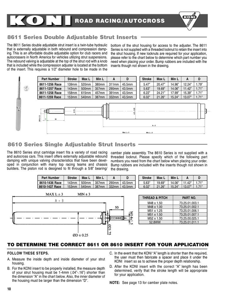
I use Koni race inserts on my race cars. The shortest cartridge length is 11.42" whch would likely fit. It has 5.42" of travel.
-
tr6racer21
- Supporter
- Posts: 307
- Joined: 07 Mar 2008 10:18
- Location: Richmond, VA
Re: Chasing J's
Plenty of travel Dave